With the experience of more than one year of patching (although you might say that this is not a lot), I’m now used to problems that I can solve after some time, but without being able to tell what the problem has been (neuronal health? osmolarity of the intracellular solution? pipette tip shape? … ?). Especially electrical noise is sometimes tricky to track down, and attempts to improve the noisiness often tend to be fruitless, or successful, but without a clear understanding what happend. See for example this anecdotal report on denoising a setup that starts with: “For three weeks I have been banging my head against the wall.”
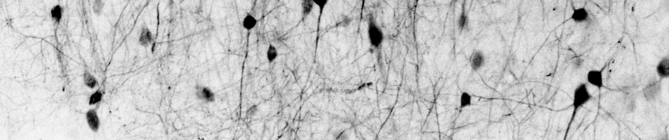
Here, I would like to show one example where I was not only successful in removing a noise artifact, but could also understand it (to some extent). To put it in context, I had installed my electrophysiology rig, together with a system of grounding cables that worked perfectly in blocking any noise from micromanipulators or other components of the 2P microscope that I’m using for targeted shadow-patching. However, there was still a line-frequency component of 50 Hz (it’s Europe) that I could not understand or remove. It wasn’t there when I tried to debug it without a brain sample, but it was there when I started doing experiments.
It turned out that the noise came from the perfusion system. I have a persistaltic pump (this one) that is located outside of the Faraday cage. It drives the ACSF perfusion of the brain under my microscope, and apparently the ACSF was transfering the 50 Hz signal from the pump directly to my preparation. This was tricky to understand, because when I used simple distilled water for water, it did not, because of its lower conductivity, transport the noise into the setup.
For a couple of days, I tried to somehow shield the pump from the perfusion system, but since the perfusion tubings and the peristaltic pumps are too tightly connected, I didn’t manage to. Finally it was an advice from my thesis supervisor (Rainer Friedrich) that solved the problem. He suggested to ‘ground’ the perfusion. It did not make so much sense to me (the ground electrode was already in the bath, why ground it again in the middle of the perfusion tubing?), but I did try it out. At the point where the perfusion tubing goes through the Faraday cage, I cut the tubing and inserted the stainless steel tubes taken from an injection needle, which in turn I connected to ground.
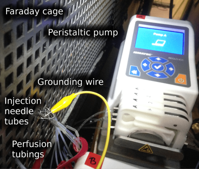
To cut the story short, it worked! It’s pretty much self-explanatory:

Pingback: Whole-cell patch clamp, part 1: introductory reading | A blog about neurophysiology
Pingback: Whole-cell patch clamp, part 4: look and feel | A blog about neurophysiology