This blog posts covers some tools and techniques that I’m typically using to align two-photon microscopes. If you’re an expert, you will probably find nothing new, but if you haven’t been doing this for years, this might offer you some pieces of inspiration.
Aligning a microscope is the process of optimizing the parts to produce better images than before. A useful overview of basic alignment procedures for two-photon microscopes has been put together in this #LabHacks blog post by Scientifica. It also includes safety advice (which I will not repeat here; keep in mind that lasers, especially pulsed IR-laser, are really dangerous, and all safety instructions of your institute and lab must always be obeyed!)
Microscope alignment still seems to be a secret art that most microscope users are afraid of. It is not by principle difficult to learn, but it is a practical skill and requires both patience and a mentor who shows where to buy stuff and how to touch the mechanical and optical elements. Most people working with microscopes are prevented from learning because they are afraid to touch anything. This blog post is intended to help lower the fear of optical alignment – by showing that the tools used for alignment can be very simple.
1. Adjust the beam to a given height above the optical breadboard
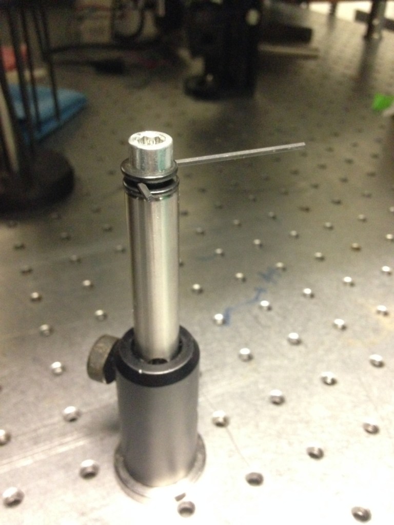
After the beam comes out of the laser, you often want to keep the beam in one single plane parallel to the table, in order to keep things simple. In other words, the distance of the beam from the optical table should be the same everywhere. One way to achieve this is to use mounted pinholes (e.g., these ones from Thorlabs). However, it is sometimes difficult to properly see where the beams hits the pinhole, which results in imprecise alignment and unnecessary uncertainty. When I worked with Robert Prevedel in 2013/2014, he showed me a simple trick which makes it very easy to adjust all beam positions to the same height. He used a small hex key and two washers to clamp it horizontally onto an inverted post with a screw, as shown below. The surfaces of the hex key lead to a very nice horizontal alignment, and the precise height indicated by the hex key can be used to (1) adjust the beam itself or (2) to consistently adjust the height of a set of pin holes. It is useful to have and very simple to make.
2. Printed-out resolution targets
Is the beam centered in a given aperture, for example the cage system of the microscope’s tube lens? Normally, I would use a threaded or cage-mounted iris (e.g., this one), but in other cases spatial constraints do not allow this, or the beam can only be viewed from an angle, and it can be difficult to judge whether the beam scattering from the iris is centered or not.
However, if the laser power is low enough not to burn paper, I simply paint resolution targets with Powerpoint or Inkscape and print them out on a sheet of paper resolution targets. When I’m in a hurry, I simply draw it with a pen.

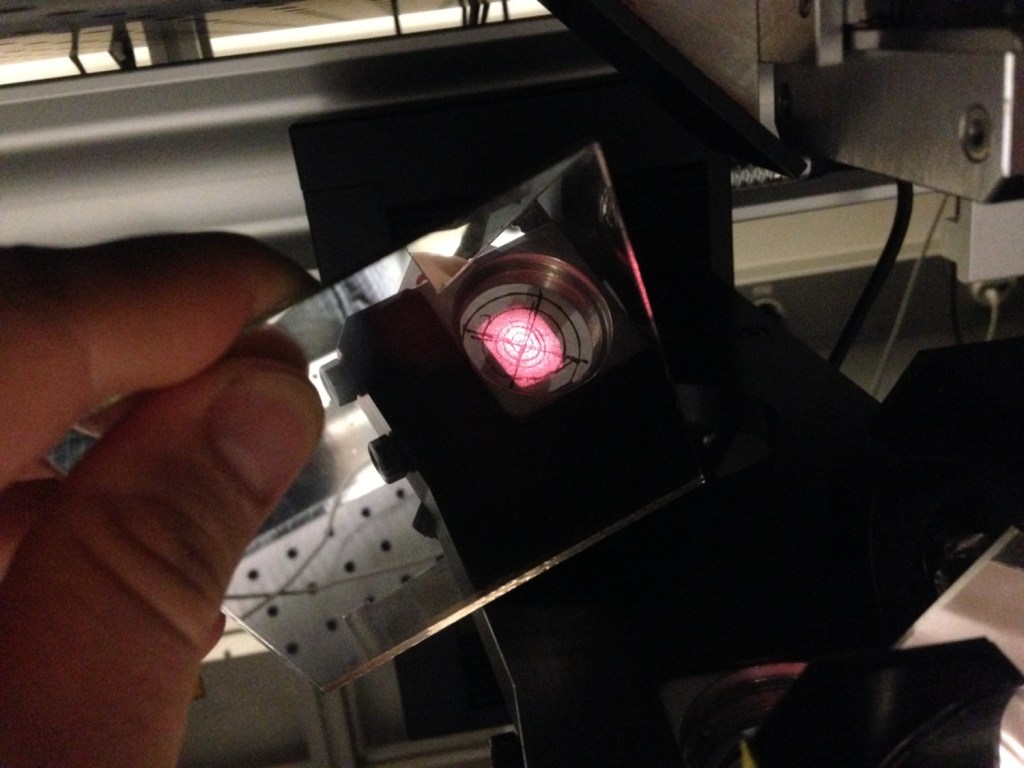
For example, if I want to check whether a beam is collimated (that means, the beam does not change its diameter a lot over the distance), I use these alignment targets as a reference and as a guide for the eye.
Or I use some scotch to fix it into a given aperture, allowing me to check whether the beam is centered or not. Here illustrated for the aperture which is approximately located at the back focal plane of the objective. Does not require much work but is quite helpful.

.
3. Using mirrors to look around corners
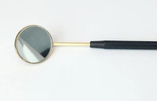
One more practical problem in the above case is the viewing angle. Ideally, I would like to look at the alignment target from the top, but this would at the same time block the beam. To solve this (and many very similar problems), you can simply use a mirror shard. The photo below (left) shows a hand-held piece of mirror which allows to look at the alignment target in a relaxed way. It is difficult to see this from a single picture, but mirrors like this one (either hand-held or fixed in the setup) often make life much easier.
For more convenience, dental mirrors like this mirror (photo below, right) are designed to conveniently look around corners and are of great use to look at pinholes from angles that are difficult to get at without mirrors.
However, be very careful with hand-held and any other moving mirrors! By chance, you might reflect the laser beam into your own eyes! Always be careful and think three times whether there is any chance that any reflection might hit your eyes.
4. Retro-reflecting mirrors and lenses
Usually, the laser beam should hit a lens at its center and at a 90° angle. To ensure that the beam is centered, one can use a) a cage system with a pinhole, or b) a threaded pinhole that can be screwed onto the lens directly, or c) a printed-out removable resolution target (see above). To make sure that, in addition, the laser beam hits the lens with a 90° angle, it is helpful to use back-reflections of the beam. Since a small fraction of the beam is back-reflected by the lens surface, it should ideally coincide with the incoming beam. This can be checked with an IR detection card or, for a visible beam, a piece of paper held close to (but not hiding the) incoming beam path.
Sometimes it is necessary to align a caged element or something similar without lenses that provide back-reflecting surfaces. In this case, you can simply use a mirror that reflects the entire beam back. This mirror can be screwed into a thread of a cage system. More often, it suffices to put a small and flat mirror shard at the flat back of the caged system. This does not provide the highest precision alignment, but is usually good enough for most purposes.
Be aware that back-reflections that go directly back into the laser can make the laser unstable. If a pulsed laser stops pulsing, first check whether any back-reflections could be the reason for it.
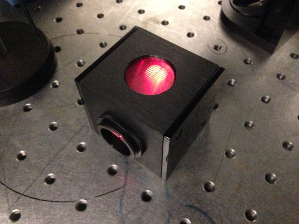
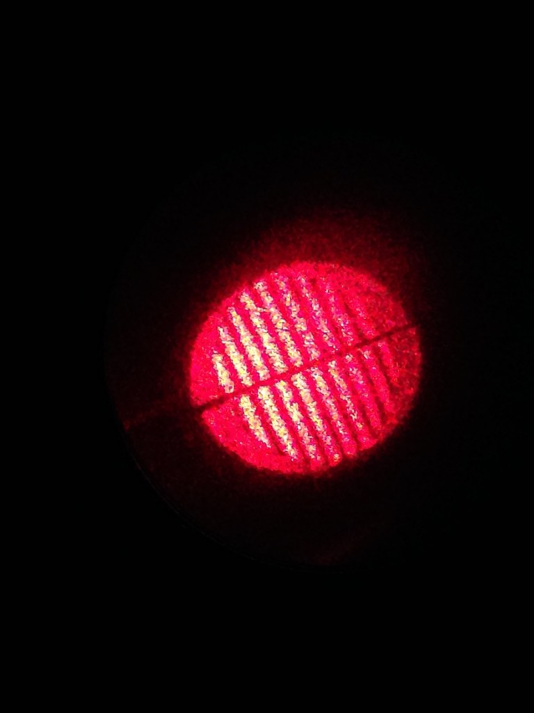
5. Retro-reflecting gratings
The main problem with back-reflections from lenses and mirrors is that the beam is often small and coincides with the incoming beam, making it difficult to properly identify.
In my PhD lab, I inherited a really cool tool that was used for alignment of a Sutter MOM scope and which I was, unfortunately, unable to find afterwards on the internet. It is basically a mirror, but with a sort of grating scratched into the mirror surface. Due to interference, the back-reflections were not simply a single beam, but a symmetric diffraction pattern that extended over several centimeters and could be conveniently used for alignment – much more useful and easier to use than the back-reflections of a lens or mirror. I guess that any flat reflective gratings (maybe even compact discs? I have to tried that) could be used for this same purpose.
6. Wedge plates
At several points of the beam path (before entering the back of the objective; after exiting a beam expander) the laser beam should ideally be collimated. The standard method that I used for years was to print out a resolution target made of paper (described above). I used it to check whether the beam changes its diameter when propagating freely over several meters. To this end, it is often necessary to deflect the beam with a mirror that must be temporarily inserted into the beam path.
Fabian Voigt from my current lab in Zürich also showed me the more professional way to check for collimation, using a wedge plate. Wedge plates can be used for shearing interferometers (Thorlabs product, EO product). They generate an interference pattern which can be used to very precisely check the collimation of the beam.
Fabian also kindly pointed me to a paper (Tsai et al., 2015) which mentions that the pattern seen from a shearing interferometer can also be used to analyze less obvious properties of the beam, like coma and astigmatism aberrations (Okuda et al., 2000). It would be cool to have a look-up table of typical interferograms and the corresponding wavefront shapes and aberrations!
7. Alignment lasers
Another tool that Fabian showed to me was an alignment laser.
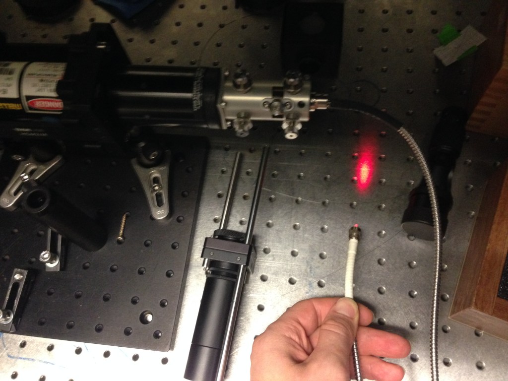
This alignment laser is basically a continuous wave-visible light laser that goes through a optical fiber and afterwards enters a beam coupler. I used a shearing interferometer (described above) to make sure that the outgoing beam was collimated, and then used the collimated beam for backward alignment.
Backward alignment means to insert the collimated beam of the alignment laser at the location of the microscope’s back focal plane and then aligning the microscope’s components in a backward manner (tube lens -> scan lens -> scanners -> etc.; instead of forward alignment, which starts at the pulsed laser and goes forward until it ends up at the objective). This is helpful for example when two or more separate incoming beams are combined. A second advantage of the alignment laser is that the laser beam is, unlike the near-IR pulsed laser, visible to the human eye.
8. Continuous wave (cw) mode for a pulsed Ti:Sa laser
Standard two-photon microscopes are based on pulsed lasers that have a center wavelength adjusted between 800 and 1000 nm. The light is therefore invisible to the human eye (except for some faint spectral components when the center wavelength is adjusted to 800 nm) and comes with high average power (>1 W, or often much more) and in ultra-short high-energy pulses, making it a very dangerous thing to deal with. IR viewer cards and IR viewers, or less expensive solutions based on simple cameras/webcams, can make the beam visible to our human eye, but I always found this very exhausting to work with. And being exhausted is not a good pre-condition for optical alignment, which requires the ability to stay focused and a sharp mind. Therefore, it would be great if it was possible to make the laser less dangerous: by preventing it from pulsing, by lowering the overall power, and by making it visible…
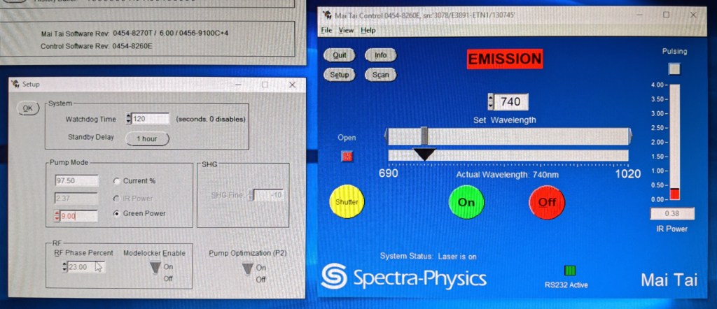
Fortunately, all of this is possible for the tunable wavelength Ti:Sa lasers (although not for the fixed 1040 nm lasers). For the Spectra Physics MaiTai lasers, the slightly old-fashioned user-interface (screenshot below) allows to manually lower the pump power (also called the “green power”). Change the wavelength to something visible (something between 700 and 750 nm), lower the green power until the pulsing (indicated by the green light in the main control window) stops and continue lowering the green power until the output IR power reaches something like 30-40 mW. This is still much more than the average laser pointer and still dangerous, but less so than a pulsed invisible beam.
It is however important to keep in mind that the control panel is not always 100% reliable. It switches between pulsing and non-pulsing as if these were binary states. But there is a sometimes continuous transition between the two, and sometimes the laser also becomes a bit unstable and oscillates between states – so, better watch the laser for a while before you start working with the beam.
I once talked to a laser engineer from Spectra Physics who told me that it would not be ideal to leave the laser in this non-pulsing state for too long (>> 1 hours). Probably this has something to do with inefficient energy conversion and the heat generated in this process. But I have to admit that I follow this recommendation simply because I don’t know it better. Lasers are complex things, and I mostly treat them in a pragmatic way, like a black box.
9. Improvised test samples
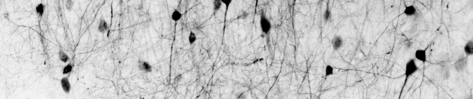
One of the most common mistakes that I keep seeing is to set up a microscope and then try to test it with a real sample, like a living brain of a transgenic mouse. That’s really not the best way to proceed. Instead, always test your microscope with a simple, bright and dead sample. (And, ideally in addtion also with sub-diffraction beads.)
For example, you can use colored plastic items (for example plastic slides), perfect to test how homogeneous the FOV is. Or pollen grains from any flowers outdoors during the pollen season. Or dead, small insects that you caught from your desk. Their surface will often be super bright under a two-photon microscope, especially if you remove the emission filters. Or simply a single strand of your hair (especially if you have still some pigments in them).
In general, most solid things are somehow autofluorescent, and it can be really fun to look at random things below the two-photon microscope. Pay attention not to kill the PMT detector (lower the initial PMT gain), since autofluorescence of natural things can be very bright.
10. More resources on (two-photon or other) optics alignment
- The Scientifica #LackHacks blog post on 2P alignment
- A classic practical guide on optical alignment by Rainer Heintzmann
- Short and focused video tutorials on optical alignment by Florian Ströhl
- A video tutorial on 2P alignment by Nemonic NeuroNex
- More advanced alignment procedures focused on adaptive optics design and alignment
- A case study of how I debugged a 2P microscope, with nice anecdotal details

The alignment laser with the optical fiber attached seems like a very useful tool! Where did you buy it?
I’m a bit late with a response for sourcing the alignment laser, but here we go: We documented the necessary parts here: https://github.com/mesoSPIM/mesoSPIM-hardware-documentation/wiki/general_alignment
Thanks for the link!
Hi Daniel, I did not buy this device myself. I assume that the laser and the fiber coupler used to attach the laser had been bought separately or taken from an old microscope, probably by Fabian Voigt (https://twitter.com/mesospim). This fiber coupler in particular was a bit finicky to use because the coupling of the laser beam into the fiber was not very stable due to worn-out screws, and any movement could change the alignment.
To get a first idea how this device can be used in principle, have a look at this video, where the ideas are explained: https://www.youtube.com/watch?v=ahDbh5UrwNc
Also, you can just google for “fiber coupler from laser”. Of course you can buy such a fiber coupler independent of the laser and attach it to lasers that you’re already using for your work.