In point-scanning microscopy and especially when using resonant scanners, the intensity of the beam is typically modulated using a Pockels cell. For resonant scanning, the dwell time per micrometer is not constant along the scanned line, and one wants either to modulate the laser intensity accordingly (here’s an example) or at least shut down the laser beam at the turnaround points, where the velocity of the scanner is basically zero for some microseconds. A command signal to shut down the laser for this period could look similar to this one on a noise oscilloscope, with the dips representing the laser beam blanking during the turnaround points:

However, sometimes the tissue is illuminated inhomogeneously, and it would be nice to increase the laser power when scanning the dim parts of the FOV. For example, in the adult zebrafish brain that I’m working with, the bottom of the FOV can be at the bright surface of the tissue, whereas the top of the image is dim due to its depth below some scattering layers of gray matter. In order to compensate for this inhomogeneity, I wanted to be able to modulate the pockels cell both in x, y, and at the turnarounds (x-direction). The problem is purely technical: In order to create a driving signal for the pockels cell on these two timescales (less than microseconds and more than milliseconds), one needs high temporal resolution and a long signal ( a long “waveform” in LabView speak). However, a typical NI DAQ board’s onboard memory is limited to 8192 data points. Which makes it impossible to modulate intensity in x and y.
I used a very simple solution to work around this problem. The idea is to generate two separate signals for modulation in x and y and then simply add the two output voltages. This does not allow for arbitrary 2D modulation patterns, but typically I’m happy with a linear combination of x- and y-modulation.
This solution disregards the non-linearity of a typical sine-shaped pockels cell calibration (input voltage vs. output laser intensity), but as long as the result is better than before, why not do it? This is what comes out:
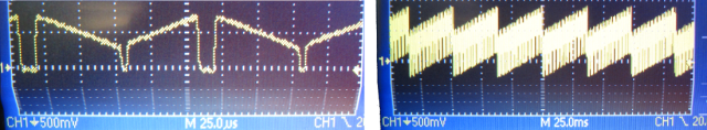
Note that the timescale is 25 microseconds on the left-hand side, and 25 milliseconds on the right-hand side.
The only technical challenge that I had to deal with was the following: From the DAQ boards, I get two separate voltage outputs. How do I sum them up? Of course, one can buy an expensive device that can do this and many other things by default. Or, one can build a summing amplifier, for less than 10 Euro:
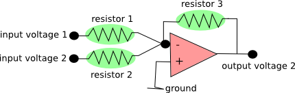
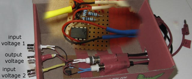
Here is a description of this very simple circuit. Just use three equal resistors (labeled green), and you have an (inverting) unity gain voltage summer. In order to maintain the temporal precision, use a MHz operational amplifier (labeled red above). I bought this one for < 1 Euro. It took me less than 30 min with a soldering gun to assemble the summing amplifier, so it’s pretty easy. That’s how it looks like in reality, with an additional zoom-in of the core circuit:
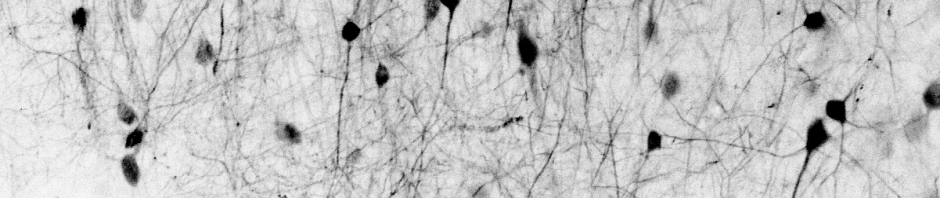
And here is a small random brain region expressing GCaMP before (left) and after (right) the additional modulation in x and y:
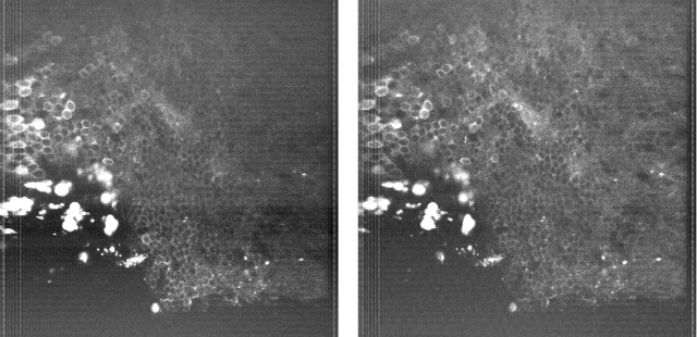
The average power is the same. The closer I looked, the more substantial the difference got. For example, the bright dura cells on the left are really annoying due to their brightness, but less so in the right-hand side image. I was surprised myself by how much this small feature improves imaging in curved brain regions, given the little money and effort it demanded.
Also, it is apparently straightforward to extend the y-direction modulation into a modulation in y and z, since the two timescales are similar (30-60 Hz framerate vs. 5-15 Hz volume rate for my experiments).

Pingback: Interesting papers on online motion correction for calcium imaging | A blog about neurophysiology