Genetically encoded calcium indicators (GECIs) are nowadays commonly used to report activity of many cells in transgenic animals; similarly, injected dyes like Rhod-2 can act as optical calcium reporters. The main shortcoming of this method is that it measures neuronal activity indirectly (via the calcium concentration), and, which is partially connected to the latter fact, at low temporal resolution (rise and decay times between 20 and 100 ms, or even more).
How nice would it be to have a genetically encoded fluorescent protein that changes its fluorescence not in response to calcium concentration, but to the electrophysiologically more relevant observable, the transmembrane voltage, better known as membrane potential. Indeed, these proteins exist. A number of recent papers made me aware of this fact; this week, I gave a short Journal Club about these indicators, and here I want to briefly summarize what is, according to my best knowledge, the state of the art.
The first voltage sensing protein constructs were published in 1997, but most sensors were lacking temporal resolution of the response, baseline brightness, response relative to baseline dF/F, or all of it. Those are the three paramters crucial for a good voltage-sensor: ideally, a voltage sensor responds quickly on transmembrane voltage changes (on the timescale of action potentials, that is < 2 ms), changes its fluorescence considerably (dF/F), and has a baseline brightness that is sufficient for imaging also in noisy and slightly autofluorescent environments.
Here’s an overview of what I found:
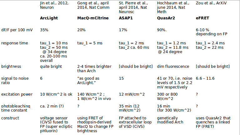
Some data on five different voltage-sensing constructs. ArcLight is included as a reference. For the four other papers, a representative construct or abbreviation is taken, e.g. QuasAr2, but there is also QuasAr1, which has slightly different properties. Some data are only what I guessed from reading the papers. Parameters differ sometimes strongly from experiment to experiment. FP = fluorescent protein, like mOrange or GFP. The response time is quantified using a (double)-exponential fit to a voltage step and varies strongly in function of the temperature. Signal to noise ratio is measured as peak signal to standard deviation of the baseline, this can be easily tweaked and is most likely difficult to reproduce in my opinion. Photobleaching time constants were not very easy to understand. it seems that some of the researchers used lower excitation power to “prove” that no photobleaching occured.
As a reference, I chose the construct ArcLight (Jin et al., 2012, Neuron, Link), because this was also taken as reference by most of the following papers. The recent constructs I had a look at were MacQ-FP (Gong et al., 2014, Nat. Comm., Link), ASAP1 (St. Pierre et al., 2014, Nat. Neuroscience, Link), QuasAr2, which is backed by a long list of co-authors, (Hochbaum et al., 2014, Nat. Meth., Link) and a method closely related to MacQ-FPs and based on QuasAr2, eFRET (Zou et al., 2014, arXiv, Link).
Generally, there a two main techniques of creating a voltage-sensing protein:
- Take a rhodopsin-like protein, the fluorescence of which changes with voltage, e.g. Arch. Then modify it by directed and random mutations in order to get better brightness, fast kinetics and higher dF/F. That’s what QuasAr2 is, a mutation of Arch.
- Take a voltage-sensing protein domain (VSD) and fuse it to a bright fluorophorescent protein. If you’re lucky, the change of the VSD configuration following a voltage change either influences mechanically the fluorescent protein (e.g. ASAP1) or acts as a fluorescence quencher (FRET acceptor) for the fluorescent protein and therefore changes its fluorescence (MacQ-FP, eFRET).
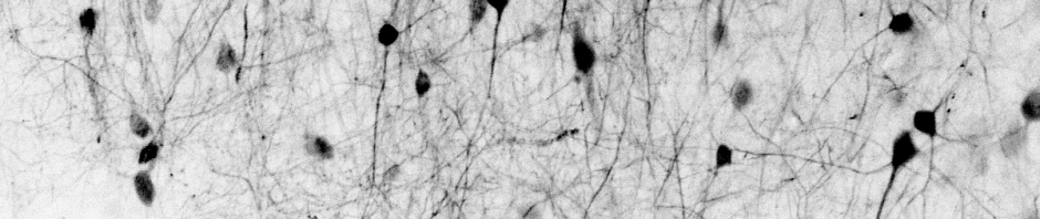
The advantages of the first approach are quite striking: very fast kinetics (response times up to 0.5 ms!), high dF/F (up to 90% per 100 mV) and high photostability. This allows to make some very impressive recordings using the QuasAr sensor. The paper combines it with an optogenetic actuator and shows some very nice imaging of propagating voltage and action potentials (some averaged over many action potentials, some not). On the other hand, these constructs are very dim compared to fluorescent protein-derived sensors like GCaMP and would most likely be drowning in noise and autofluorescence when applied in vivo.
The second group of voltage sensors has lower dF/F, and also the kinetics is slower (MacQ and eFRET try to compensate for this drawback by using an Arch-derived FRET-quencher, but they do not manage to unite the best of both worlds). On the other hand, these sensors are much brighter, and one paper also tries to apply their sensors (MacQ-FP) in vivo to record optically dendritic calcium spikes in Purkinje cells of the mouse cerebellum. The action potentials have a dF/F of ca. 1% only, and the researchers do not manage to record whole cell-currents simultaneously, because the vibrations induced by the electrical recording makes the optical recordings unfeasable … maybe they were under time-pressure, feeling all these other papers emerging from every side; but still this shows how far the voltage-sensing proteins are from being applied easily in living animals.
But what would actually happen if we were able to combine the response time of QuasAr1 (0.5 ms or less) with a high dF/F (say 300% per 100 mV) and a brightness comparable to GCaMP (which is not so high for GCaMP6)? First, it would be necessary to record with high speed (1000 Hz or even more) in order not to miss action potentials. Some cameras achieve this high speed, if the read-out area is reduced to a fraction of the full sensor. Roughly, a sCMOS camera can read out a 200×200 px region with 1000 Hz. This would allow to do voltage-sensing of very few neurons (maybe two or three which are close to each other) with good spatial resolution of possible dendrites in this plane. For non-superficial layers, this method cannot be applied due to scattering in tissue, and two-photon scanning methods would be applied. Resonant scanners can be driven with up to 16 kHz (e.g. http://www.eopc.com), allowing for a line rate of 32 kHz in bidirectional scan. If we want to sample at 1000 Hz, we have 32 lines or less at our disposal. This could still be enough to get reasonable results for few neurons if not every dendrite needs to be resolved. Alternatively, fast AODs used for dendritic imaging have achieved line rates of up to 80 kHz (Chen et al., 2012, link). Note that also the repetition rate of the laser would come into play, because it would pulse only 1000 times during one line – this needs synchronization, otherwise it will add strange beat patterns upon the image. Ok, let’s say we need only a 500 Hz frame rate, even if we might miss some transient dendritic events. Then we would go to 160 lines vertically.
What is the limit? Maybe one limit is the fluorescence lifetime, being aroung 2-3 ns for typical fluorophors. Deep in scattering tissue, we can therefore only sample pixels with a frequency < 1/2 ns = 500 MHz. At 500 Hz sampling rate, we would get 1000^2 sampling points to spread. This is enough for ca. 4 planes of 512×512 pixels, assuming 1) scanning takes no time, 2) one laser pulse (repetition rate of 500 MHz) is sufficient to get enough flourescence, 3) the fluorescence lifetime is < 2 ns, otherwise the fluorescent photons will blurr into the next pixel. This would already be quite ok; but it would still be only a small window into the brain, and even smaller, if dendrites are to be resolved, and with only few imaging planes. This would allow to check the temporal spread of activity between some neurons, and, if all this worked technically, it would be possible to do voltage-sensing in ROIs with some 10 neurons in vivo. But I do not see the technology to go beyond these limits.
