Calcium imaging with two-photon point scanning is the technique to chronically record from identified neurons in the living brain of animals. The central piece of two-photon point scanning microscopes is a scan engine. This can be a complex optical device like a deformable mirror or an acousto-optical deflector; but more often, it is just a mirror sitting on a rod and scanning forth and back as fast as possible. The fastest such mirrors are so-called resonant mirrors.
Currently, there is only one major provider of resonant scan mirrors for microscopy, and only few months ago, the lead times had risen to >1 year. Resonant mirrors are therefore much more precious than their mere price tag, and it is worth trying to get the best out of existing resonant scanners, instead of replacing them with new scanners at the sight of the slightest problem.
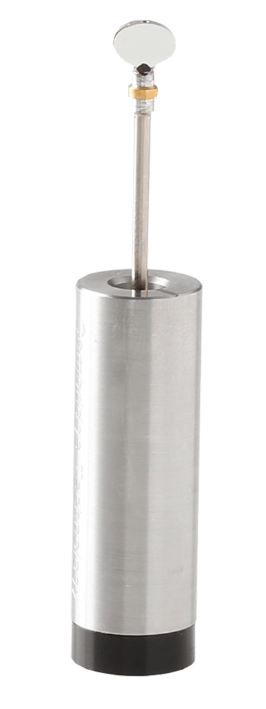
Figure 1. A typical resonant scan mirror, mounted on top of an oscillating rod. Adapted from https://novantaphotonics.com/product/crs-resonant-scanners/
Recently, I have been working with Johanna Nieweler, a PhD student in the Helmchen lab, to piece together her two-photon microscope from the remains of a previous microscope. Among the surprisingly numerous problems that Johanna encountered and fixed during this work was a problem that was ultimately due to the resonant scanner. In this blog post, I will describe how we identified the problem and came up with a – in my opinion – very elegant solution. This might be a useful resource for optical engineers who are dealing with similar problems and for microscopists who want to understand more about resonant scanners.
A periodic line jitter for high-zoom scanning
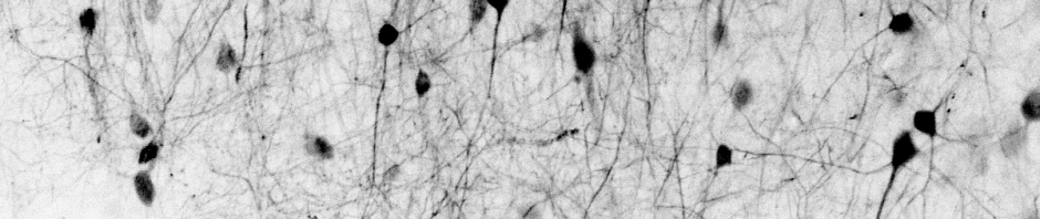
The problem was not immediately apparent. An image of small fluorescent beads acquired with the scanning microscope looked fine when zooming out:
However, to evaluate the imaging quality, but also for real experiments that resolve subcellular structures, zoomed-in imaging is essential. In our case, we noticed some kind of irregular distortion of the scan pattern, as if the beads were changing their shapes or dancing around:
To better understand this distortion, we switched off the slow galvo scanners and performed a line scan with the fast resonant scanners only. This configuration clearly revealed a periodic jitter of the scan phase of the resonant scanner.
Such an artefact could be due to many possible sources. First, it could be that the software to acquire and bin the incoming data stream might have a bug. Second, there could be a vibration responsible for sample movement. Third, it could be some line noise coupling into the “sync signal” emitted by the resonant scanner. Fourth, the mechanical scanning itself could be governed by this period modulation.
Finding the problem
The resonant scanner under scrutiny was a 4 kHz resonant scanner from Cambridge Technology. First, we measured the periodicity of the signal distortion – the frequency was around 270 Hz. So it was unlikely to be line noise, which is at 50 Hz or multiples thereof in Europe.
Next, we also did not find any vibrations that might have caused this problem.
We checked and replaced the the power supplies of the resonant scanner, without any improvement.
Finally, we turned our attention to the resonant scanner. The resonant scanner produces a so-called “sync signal”, which is a TTL signal that indicates whether the scanner is moving in the clock-wise or counter-clockwise direction. At the turning point of the directional change, the scanner flips the TTL signal and therefore generates the electrical trigger signal for the next line of the imaging frame. This means that an imprecise generation of the TTL signal, or a wobbly oscillation of the mirror itself could generate a jitter of the TTL signal and a modulation of the line signal as we observed.
Indeed, when we looked at the sync signal on the oscilloscope (we triggered on a rising flank and looked at the oscilloscope on the subsequent rising flank of the TTL), we observed a jitter of the signal that would explain the artefact in the image.
Now, this jitter could be due to a physically wobbling scan mirror; or due to an imprecise readout of the turnaround point by the TTL signal generator at the resonant scanner. Is it possible to distinguish between these two options? Yes, it is. If the scanner is scanning properly and only the TTL signal generation is affected, one could in theory simply replace the periodic TTL signal and then observe an artefact-free image.
We therefore replaced the bad TTL signal with an artificial TTL produced by a signal generator, at the exact same frequency as the resonant scanner’s frequency. Fascinatingly, we observed that this procedure fixed the problem beautifully. One can also notice that the picture drifts away if the signal generator frequency does not exactly match the frequency of the resonant scanner:
Despite this limitation, we concluded that the scanner was apparently not wobbling around, and only the generation of the TTL signal was defective.
From a workaround of the problem to a permanent and user-friendly solution
But there is a problem – we cannot simply use the signal generator with a fixed frequency TTL signal and hope that things will be fixed. First, the resonant scanning frequency of any resonant scanner changes slightly over time as it warms up. Second, the resonant scanning frequency also varies (a few fractions of a percent) when the zoom level of the microscope and therefore also the scan amplitude of the resonant scanner is changed. A mismatch between the scanner’s frequency and the sync signal would result in the drift that is visible in the video above.
What we therefore needed was a system that uses the jittery TTL sync signal of the resonant scanner and produces an output that is phase-locked to the sync signal, but without the jitter …
At this point, I vaguely remembered that this can be achieved by a simple analog electric circuit, and after an internet search, I found the Wikipedia article on the “phase locked loop” (PLL), which described exactly what we were looking for. A PLL uses an input (in this case, a jittery TTL signal) and creates a synchronized TTL signal that is typically phase-locked and runs at the same frequency but without jitter when the feedback is filtered appropriately. So we only had to implement this circuit, insert this device between the scanner’s sync signal and the “line trigger” input channel of the DAQ board, and our images would look perfectly line-triggered!
The problem here is that neither Johanna nor I had been trained as electrical engineers, so we would have struggled to translate this relatively simple idea into a working device. However, there was a true expert and lover of electrical circuits at the Brain Research Institute in Zürich: Hansjörg Kasper. Working as a support engineer at the institute for several decades, he was not only an expert for basically any practical technical question ranging from laser physics to soldering techniques, but he was also very familiar with analog circuits. While nowadays often replaced by micro-processor-based solutions, analog circuit elements such as PLLs had been standard components of electrical engineering 30-40 years ago and therefore very familiar to Hansjörg. For example, he had used PLLs in a system that he designed more than twenty years ago to track head and eye movements of small animals.

Hansjörg was quickly intrigued by our problem and accidentally had such a phase-locked loop circuit at his hand, the “classic” – as he called it – CD4046 PLL element.
Figure 3. Photo of a CD4046 PLL circuit, https://www.ti.com/product/CD4046B.
By the way, these circuits are quite cheap (<10 Euros). Within one day, Hansjörg soldered the components together to produce the desired behaviour. To this end, he followed the instructions that come with such a circuit element, indicating how to choose resistors and other elements to produce the desired behaviour.
He sent me this circuit diagram of his final circuit, optimized for stabilizing the sync signal of a 4 kHz resonant scanner:
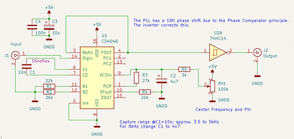
Figure 4. Circuit diagram of a PLL circuit based on a CD4046 element. An inverter (“U2A 74HC14”) is included to generate a signal with the same phase shift as the input signal. At the bottom, it is indicated how to re-dimension the capacitor C1 in order to optimize the circuit for a 8 kHz instead of for a 4 kHz resonant scanner. Drawing and annotations were done by Hansjörg Kasper in KiCad.
Soldering this circuit requires a bit of practice but could be learned rather quickly by any talented tinkerer. The true challenge, in my opinion, is to start with the CD4046 datasheet (or the datasheet of a similar PLL circuit) and figure out how everything must be connected. It is not much more than 5 pages of the datasheet that are relevant, but I would probably not have understood it easily without Hansjörg’s explanations. Hopefully the circuit diagram above provided by Hansjörg will make it easy for anybody who will try to replicate our PLL stabilizer!
How it works
The circuit turned out to work beautifully. We hooked it up to the microscope, and within days we had already almost forgotten that it existed – this is a true hallmark of great engineering: that the problem is solved so perfectly and robustly that you quickly forget about its mere existence. Here is the stabilized line scan, in direct comparison with the line scan without stabilization. The residual slow wiggling of the line is due to 50 Hz line noise (a different problem).
And the same FOV with a regular scan pattern, which showed the bead without the additional dance moves, therefore enabling us to clearly see the point spread function:
If there is anybody out there struggling with a similar resonant scanner problem, I hope that this blog post will give them the tools to address and solve this problem!
In the end, I was curious whether the same solution could also be helped to generally stabilize resonant scanners. Resonant scanners are known to become “wobbly” with age or when scanning with low amplitudes (high zoom-in). I was simultaneously working also on another two-photon resonant scanning setup with an 8 kHz scanner, and I noticed some sort of wobblying and instability for very high zoom settings. Therefore, I used a signal generator to provide a highly stable sync signal to replace the scanner’s sync signal. Unfortunately, no improvements of the imaging quality could be observed. Apparently, in this case the resonant scanner was indeed wobbling physically, while the 4 kHz scanner was oscillating properly and only the generation of the TTL signal was compromised.
Altogether, this small engineering project with Johanna and Hansjörg was, in my opinion, extremely interesting and valuable. Growing up in the age of Arduinos and Raspberry Pis, where every problem can be solved by a bit of code running on a microprocessor, it was impressive to be reminded of the power of analog circuits. Of course, this implementation was only possible because we had an expert for and lover of analog circuits, Hansjörg Kasper, in our institute.
P.S. Hansjörg had been at the heart of the institute for more than 40 years. He retired officially in 2022 but did the work for this PLL project while working part-time at the Brain Research Institute in the Spring of 2023. Unexpectedly and unfortunately, he died in the early Summer of 2023.
During his time at the institute, his work had helped many dozens of PhD students and postdocs tremendously, by solving many small and big technical challenges that typical scientists are rarely equipped to address by themselves. Many a small device and machine that was built during his era, from synchronization boxes for behavioural setups to our small PLL circuit, will continue to run in the labs of the Brain Research Institute in the future, many years after him.
P.P.S. Big kudos to Johanna Nieweler, together with whom I worked on this project, to Hansjörg Kasper (R.I.P.), who designed and built the PLL circuit, to Martin Wieckhorst, who helped with the first brainstorming about the PLL circuit, and to Fritjof Helmchen, who supervises both Johanna and me.

Nice! Thanks for sharing this. -Spencer
This is great work. I reached the same conclusion about the stability of the sync signal from an 8Khz CRS scanner. My solution is not to use the sync signal at all, but instead use the velocity feedback and some good signal processing in an FPGA – my whole system is built inside an FPGA. The problem is with the CRS driver boards – I plan to design my own one day.
Thanks! It’s interesting to know that the problem is not mechanical but with the CRS driver boards. If you ever design your own driver board, I’d be very curious! And if I ever have to fix this issue again, I will also have a look into the velocity feedback signal as you’ve done.
May you share your method and the result?
Have you tried the resonant scanners from EOPC (www.eopc.com)?
No, I haven’t tried EOPC scanners.
It could be that such artifacts as described in the blog post are vendor-specific. However, I have recently heard of a case where a Thorlabs 8 kHz scanner showed a similar kind of jitter. The conclusion was that it was defective, and it was sent back for replacement. Maybe resonant scanners, not matter from which company, may have a tendency to produce such jitter, while other scanners of the same series might be working correctly.